 How to Start an EV Charging Business in 2026 for Commercial Sites
Mar 23, 2026
Many EV charging projects do not struggle because of charger quality alone. They struggle because the site, power plan, permit path, and operating model were never aligned from the start.
Starting an EV charging business in 2026 takes more than visible demand and a hardware budget. A workable project begins with the right charging use case, realistic site conditions, clear operating responsibilities, and a practical view of cost and return.
For site owners, operators, property managers, and commercial buyers, the first question is not which charger to buy. It is whether the site can support a reliable charging business before installation begins.
Choose the Right Charging Use Case
Not all EV charging businesses work the same way. Many weak projects start with the assumption that they do.
A highway fast-charging site, a hotel parking area, an office campus, a fleet depot, and a residential property may all need EV charging, but they do not follow the same demand pattern, investment logic, or operating model. That difference should be defined first, before charger selection or ROI planning begins.
Public fast charging
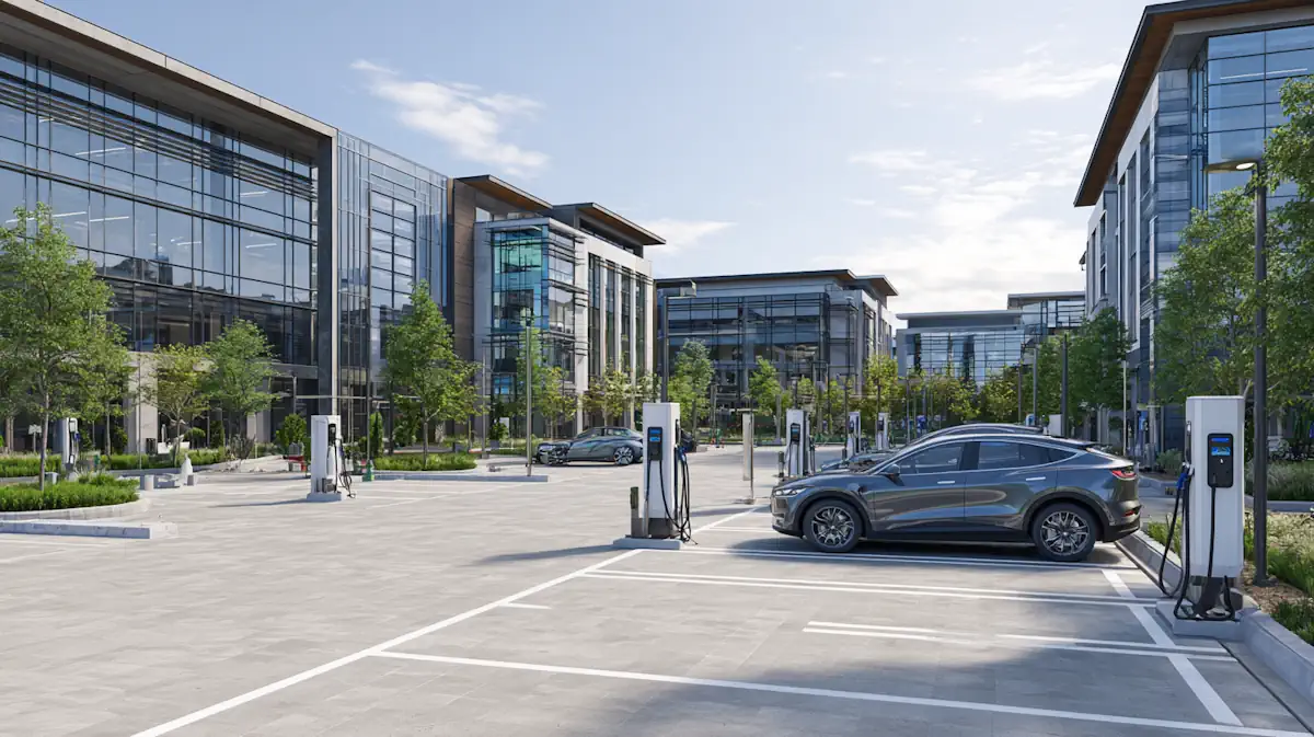
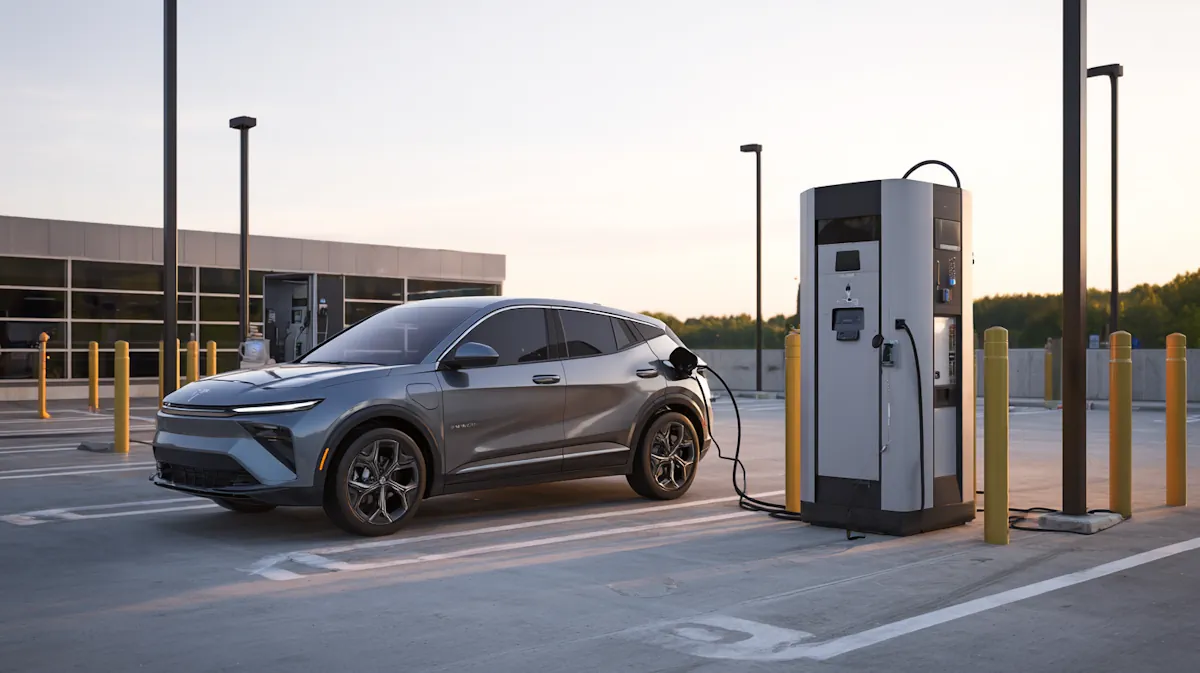
Public fast charging works best where drivers need quick, reliable energy and are unlikely to stay long. Highway corridors, urban traffic hubs, and visible roadside sites often fit this model. In these environments, the business case depends on throughput, uptime, easy access, and enough power capacity to keep vehicles moving.
Destination charging
Destination charging works differently. Hotels, retail centers, restaurants, tourist sites, and mixed-use properties usually benefit from longer parking duration. Charging supports the broader visitor experience, and the value may come from more than charging revenue alone. Longer stays, better site appeal, and stronger service differentiation can all matter.
Workplace charging
Workplace charging is usually less about turnover and more about convenience. Offices and business parks tend to have predictable parking patterns, which makes them suitable for lower-power charging that fits daily schedules rather than urgent demand. The value often comes from employee support, tenant experience, and long-term property competitiveness.
Fleet and depot charging
Fleet and depot charging should be treated as a separate category. Commercial vehicles run on planned routes, fixed return windows, and strict readiness requirements. The charging strategy must support dispatch planning, energy management, and reliable scheduled charging. In these projects, operational continuity matters more than public visibility.
Multi-family charging
Multi-family charging often depends on shared parking conditions, electrical upgrade limits, property management decisions, and future resident demand. These projects need a practical balance between installation cost, daily usability, and room to scale. The first rollout may be small, but the site should not create unnecessary expansion problems later.
The key question at this stage is simple: what kind of charging environment are you actually building? Once that answer is clear, the rest of the project becomes easier to evaluate. Site planning, power requirements, operating structure, hardware selection, and ROI expectations all become more realistic when the use case is defined first.
EV Charging Use Cases
Use Case
Typical Site Type
Main Value Driver
Key Planning Priority
Public fast charging
Highway corridors, urban hubs, roadside sites
Throughput and uptime
Power capacity and access
Destination charging
Hotels, retail centers, mixed-use sites
Visitor experience and dwell time
Parking duration and site fit
Workplace charging
Offices, business parks
Employee convenience and property value
Daily parking patterns
Fleet and depot charging
Logistics yards, bus depots, service fleets
Vehicle readiness and operational continuity
Energy planning and charging schedule
Multi-family charging
Residential communities, shared parking properties
Resident convenience and long-term support
Electrical upgrades and scalability
Check Site Feasibility First
Once the charging use case is clear, the next step is to test whether the site can actually support it. This is where many promising plans begin to change.
A location may look attractive on paper and still perform poorly as a charging site. A busy site is not automatically a strong charging site. What matters more is how drivers use the location, how long they stay, whether they have a reason to charge there, and how often they are likely to return.
Traffic, dwell time, and user behavior
Traffic volume alone is not enough. A site with moderate traffic and long parking duration can sometimes support a stronger charging business than a site with heavy traffic and no meaningful dwell time.
Power and upgrade risk
Power availability should be checked early. Existing electrical infrastructure may be enough for a small installation, but higher-power or scalable deployments often require service upgrades, added coordination, or a longer implementation path. In many projects, the charger is not the hardest part. The supporting electrical work is.
Layout, access, and expansion potential
Physical layout matters just as much. Charger placement, parking orientation, cable reach, traffic circulation, accessibility, safety, and equipment protection all affect whether the site will operate smoothly. A location can seem suitable at first glance and still create daily problems if vehicle access is awkward or future expansion has not been considered.
Expansion potential should be checked early as well. Some sites are planned only for the first phase, with little thought about what happens if charger use grows. If the project may need more charging points later, the layout, conduit planning, electrical design, and site access should not make that growth unnecessarily difficult or expensive.
Charger selection should come after site feasibility, not before it. When the site is wrong, even strong hardware will struggle to produce a reliable business outcome. When the site is right, the rest of the project becomes much easier to plan with confidence.
Address Permits and Utility Planning Early
A viable site does not guarantee a smooth project. This is where many charging plans begin to slow down.
The problem is usually not hardware alone. It is often the permit path, utility coordination, or site compliance work that takes longer than expected. When these issues are treated as late-stage tasks, both schedule and budget become harder to control.
Permits and approval timelines
Commercial charging projects often involve more than a simple equipment install. Local approvals, electrical review, construction-related checks, and final inspections can all affect the timeline. Even when the charger scope appears straightforward, the approval path may not be.
Utility coordination and service upgrades
Utility coordination should start early, especially if the site may need a service upgrade or added capacity. This becomes even more important for DC fast charging, multi-point deployments, or projects with future expansion plans. In many cases, the electrical path shapes both the launch schedule and the cost structure long before installation begins.
Accessibility, safety, and site design
Compliance is not just paperwork. Accessibility, safety, site circulation, equipment placement, and user access all influence how well the charging system will work in daily use. A design that only aims to pass review may still create operating problems later.
Permits, utility coordination, and compliance are not boxes to check after the business case is built. They are part of the business case. They affect timing, budget, site design, and project risk from the start.
Choose the Right Operating Model
After the use case, site conditions, and project constraints become clearer, the next question is how the charging business will actually operate. That is different from deciding where chargers will be installed. It is about who will invest, who will manage daily operation, who will handle support and maintenance, and how value will be created over time.
Owner-operated charging
In an owner-operated model, the site owner or project sponsor keeps direct control over the charging business. This approach gives the project more flexibility in pricing, service standards, customer experience, and long-term planning. It can also create stronger revenue control when the site already has clear charging demand. The trade-off is responsibility. The operator must be ready to manage uptime, maintenance coordination, payment systems, and day-to-day service expectations.
Third-party operated charging
A hosted site does not always need to operate the charging system itself. In a third-party-operated model, the property provides the site while another party handles some or most of the charging operation. This can reduce the burden for hotels, retail sites, property owners, or business parks that want to offer charging without building a full internal charging function. The trade-off is lower control over pricing, service structure, and future operating changes.
Private charging for fleets
Fleet charging follows another logic. The goal is not always public revenue. In many fleet projects, the real value comes from vehicle readiness, route continuity, lower fueling disruption, and better energy planning. Here, the charging system should be evaluated as part of the wider transport operation, not as a standalone public charging business.
Where the value comes from
Revenue logic changes by site type. Some projects depend mainly on charging income. Others create value through parking revenue, longer customer dwell time, tenant support, employee convenience, or operational efficiency. A workable operating model does not copy what other sites are doing. It matches the property, the users, and the business goal behind the installation.
Before moving ahead, the project should have clear answers to four questions: who pays for the system, who operates it, who supports it after launch, and how the site expects to create value from it. If those answers are vague, the operating model is not ready yet.
Choose Hardware and Software That Fit the Project
Hardware selection should follow site logic, not lead it. Once the use case, site feasibility, permit path, and operating model are clear, equipment choices become easier to align with the actual project.
When AC charging makes sense
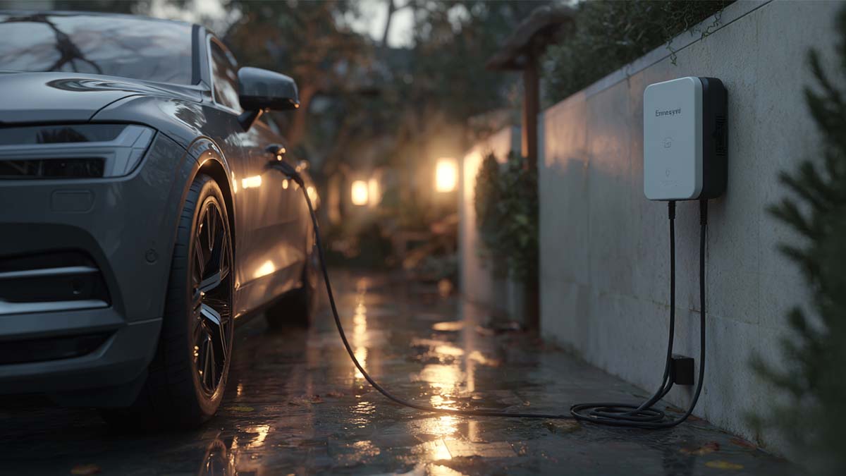
AC charging usually makes sense where vehicles stay longer and charging does not need to happen quickly. That often includes workplaces, hotels, residential properties, and other sites where dwell time supports lower-power charging. For many of these projects, the goal is convenience and steady access rather than rapid turnover.
When DC charging makes sense
DC charging makes more sense when the site depends on faster turnaround, stronger throughput, or higher daily charging demand. Public fast-charging locations and some fleet environments often fall into this category. In these cases, power capacity, thermal performance, uptime, and maintenance readiness become much more important.
Power range and connector fit
Power range and connector selection should reflect real use, not trend-driven assumptions. A project does not become stronger simply by choosing higher-power equipment. It becomes stronger when the equipment matches vehicle behavior, site role, and expected operating conditions. For businesses planning commercial deployment, this is also the stage to assess component reliability, serviceability, and long-term supply support.
Software, payment, and monitoring
In commercial charging, software is not an add-on. It is part of daily operation. Payment handling, remote monitoring, user access, basic reporting, and maintenance visibility all influence the charging experience after launch. A charging system that works on paper can still become difficult to manage if the software layer is weak.
What to ask hardware and service partners
The right questions are not only about product specifications. They are also about certification status, integration capability, maintenance support, response time, and deployment experience. Stronger projects choose equipment and partners based on operational fit, not just catalog appeal.
Estimate Costs and ROI Realistically
Cost estimates become more reliable only after the operating model is clear. This is where many charging projects either become stronger on paper or begin to fall apart.
Upfront costs
A rough hardware budget is not enough. The charger may be the most visible part of the investment, but it is rarely the whole picture. Installation labor, civil works, trenching, mounting, electrical upgrades, protection measures, and site preparation can all reshape the budget quickly.
Ongoing costs
Ongoing cost matters just as much. Software fees, network services, maintenance support, energy cost, demand charges, inspections, and repair response all affect long-term performance. A project can look attractive at the purchase stage and still become difficult to operate if recurring cost is underestimated.
What drives payback
Return depends on more than installed power. Utilization rate, pricing structure, parking duration, uptime, user mix, electricity cost, and operating efficiency all influence payback. A public fast-charging site does not behave like a workplace site. A fleet charging system may create value through vehicle readiness and operational control even when direct charging revenue is not the main goal.
There is no universal ROI formula for every charging business. Two projects with similar hardware can produce very different results because the site conditions, user behavior, and operating model are different. If the ROI only works under one optimistic assumption, the business case is probably not ready.
The goal at this stage is not to force the project into one perfect payback number. It is to understand which variables matter most, where the budget risk sits, and what level of usage or value creation would make the project commercially reasonable.
Follow a Practical Launch Process
A charging project becomes easier to manage when the launch process follows a clear order. Many avoidable problems appear when teams move too quickly into procurement or installation before the early decisions are stable.
Step 1: Validate the use case and site fit
The project should already know who the users are, why they would charge there, how long they are likely to stay, and whether the location supports the intended model.
Step 2: Confirm power and utility conditions
This includes checking existing electrical capacity, upgrade risk, and whether the intended deployment is realistic for the site.
Step 3: Define the operating model and value logic
Before equipment is finalized, the project should be clear on who will run the system, who will handle support, and how value will be created after launch.
Step 4: Finalize permits, hardware scope, and software needs
By this point, charger selection, payment setup, monitoring tools, and approval coordination should all align with the actual business goal.
Step 5: Install, test, and prepare for launch
This stage should include commissioning checks, user access planning, payment flow verification, and early support readiness.
Step 6: Monitor and adjust after launch
Real usage often exposes issues that were not obvious during planning, so uptime, user behavior, parking flow, payment experience, and actual utilization should all be reviewed after launch.
Common Planning Mistakes
Many charging projects do not fail because the market opportunity was weak. They fail because key decisions were made in the wrong order.
Starting with chargers instead of site conditions
Hardware decisions made before site fit, power capacity, and user behavior are understood often create mismatch later. A strong charger cannot correct a weak project foundation.
Underestimating permit and utility timelines
Some projects assume approvals and electrical coordination will move quickly because the charging scope looks straightforward. In practice, these factors can affect both schedule and cost much more than expected.
Using a generic ROI assumption
Charging businesses do not perform the same way across all sites. Revenue, cost, and value creation depend on the use case, operating model, dwell time, utilization, and long-term maintenance reality.
Ignoring post-launch operations
Installation is not the end of the project. If uptime, support, software visibility, user access, and maintenance response are not planned clearly, the charging system can become difficult to manage even when the hardware itself is sound.
Final Checklist Before You Invest
Before moving forward with an EV charging project, the site should be able to answer a few basic questions with confidence.
• Is the charging use case clearly defined?
• Does the site have the right traffic pattern, parking behavior, and user demand?
• Is power availability realistic for the intended charging scope?
• Are permit, utility, and compliance requirements understood early enough?
• Is the operating model clear, including responsibility for service and support?
• Do the cost assumptions and ROI expectations reflect the actual site conditions?
A workable EV charging business in 2026 starts with better decisions before installation begins. The strongest projects are not the ones that move fastest into hardware. They are the ones that match site conditions, operating structure, and long-term business goals from the start.
For businesses moving from planning to deployment, hardware fit and project support matter just as much as the initial business case. Workersbee supports commercial EV charging projects with charging connectors, portable charging solutions, and related supply capabilities designed for real deployment needs.
Read More

 CCS1 Connector Selection Guide for North American DC Fast Charging Projects
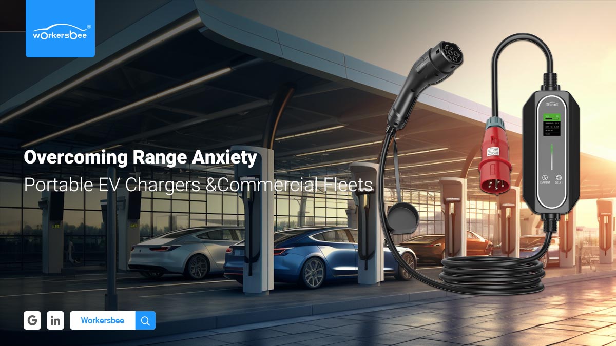 How Portable Charging Helps Commercial Fleets Reduce Range-Related Risk
 Extension Cord for Portable EV Charging: Safety Checklist and Heat Test
 Precision Machining Capability: Swiss Turning, CNC Milling, Materials, and Inspection
 UK 3-Pin (BS 1363) Granny Charging: A Practical Safety Checklist for Portable EV Chargers
 Charging on Schuko (Type E/F): Safe Use for Portable EV Chargers
 CEE (IEC 60309) Red 3-Phase 16A vs 32A for Portable EV Charging
 CEE (IEC 60309) Blue 16A vs 32A for Portable EV Charging
 NEMA 6-50 vs 14-50 Outlet Guide for Portable EV Charging
 NEMA 14-50 for Portable EV Charging: What to Check First
 Portable EV Charger Power Plug Guide: NEMA vs IEC 60309 vs Wall Sockets


 English


 IPv6 network supported